
Please Choose Your Language


Views: 0 Author: Site Editor Publish Time: 2026-10-08 Origin: Site


Deploying high-capacity charging infrastructure requires a careful balancing act for Charge Point Operators (CPOs) and fleet managers. You must weigh upfront capital expenditure against future-proof utility. A 160 kW DC fast charger represents a highly effective commercial sweet spot. We frequently see them driving value across highway corridors, retail plazas, and medium-duty vehicle fleets. However, underlying hardware specifications directly dictate operational uptime and overall return on investment.
This guide cuts through common marketing claims to deconstruct critical engineering specifications. We examine voltage architectures, continuous current limits, and thermal management systems. These technical dimensions are essential to evaluate and shortlist a viable high-speed charging solution.
Our objective is to provide a transparent, evidence-oriented framework for procurement teams. You will learn how to accurately assess hardware viability, navigate complex installation risks, and understand real-world performance limitations. By mastering these specifications, you can avoid costly deployment mistakes.
A frequent business problem plagues many fast-charging deployments today. Mismatches between charger voltage limits and vehicle battery architectures result in throttled charging speeds. This technical bottleneck creates a notoriously poor customer experience. Drivers expect peak speeds but receive a fraction of the advertised power. To avoid this, operators must scrutinize the electrical parameters of their hardware.
The transition from 400V to 800V EV architectures is accelerating. Servicing modern 800V architectures, like the Hyundai E-GMP or Porsche Taycan, requires specific hardware capabilities. A wide output voltage range, typically spanning 200V to 1000V, is essential. Older 500V systems cannot push enough power into an 800V battery without relying on the vehicle's onboard DC-DC converter. This internal conversion causes severe voltage-induced derating. Operating a 1000V architecture guarantees backward compatibility with legacy 400V passenger EVs while future-proofing your site.
Understanding current delivery is just as critical as voltage. A standard 160 kW unit must deliver at least 400A to achieve peak power at lower voltage thresholds. For example, charging a 400V EV requires high amperage to hit the 160 kW mark. If a charger maxes out at 200A, a 400V vehicle will only receive 80 kW, regardless of the charger's nameplate rating.
You must also remember a fundamental operational reality. The 160 kW figure is a theoretical peak. Actual power delivery is strictly bound by the vehicle's Battery Management System (BMS). The BMS dictates the exact current it will accept to protect battery health.
Power conversion from AC to DC generates inherent energy losses. You should target hardware with greater than 94% peak efficiency at full load. A mere 2-3% drop in conversion efficiency significantly increases lifetime energy waste. This inefficiency directly inflates your monthly electricity overhead.
Charger Architecture Comparison
| Architecture Type | Max Voltage Limit | 400V EV Performance | 800V EV Performance | Future-Proof Rating |
|---|---|---|---|---|
| Legacy System | 500V DC | Optimal (up to amp limit) | Heavily Throttled | Low |
| Modern System | 1000V DC | Optimal | Optimal | High |
Continuous high-power output generates substantial heat inside the cabinet and along the charging cable. Managing this thermal load is critical for sustained performance. Solution categories generally split into active forced-air cooling for the main cabinet and liquid-cooled systems for the delivery cables.
Heavy load cycles require robust internal HVAC or high-speed fan systems. The rectifiers converting AC to DC produce significant ambient heat. You must carefully assess the operating temperature range of the unit. Standard premium units operate reliably from -30°C to +55°C. Beyond these limits, you must know the exact point at which thermal derating occurs. When a charger derates, it intentionally reduces output power to prevent catastrophic hardware melting. This protects the equipment but extends driver wait times.
Pushing 400A or more through standard, uncooled copper creates major usability issues. The cables become excessively thick and heavy. This stiffness drastically reduces accessibility for users. Liquid-cooled cables solve this problem effectively. They route synthetic coolant alongside thinner copper wires. This reduces weight and significantly improves the overall user experience.
However, liquid cooling introduces implementation considerations. You now face coolant maintenance requirements. Pumps can fail, lines can leak, and glycol levels require routine inspection. Operators must weigh driver ergonomics against increased maintenance complexities.
High-velocity cooling fans generate substantial acoustic noise. A unit running at full capacity can easily exceed 65 to 70 dB. This noise level resembles a loud industrial vacuum cleaner. You must conduct strict compliance checks for installations near residential zones or mixed-use commercial spaces. High noise output frequently leads to community complaints and potential municipal fines.
Site layout dictates which hardware form factor works best. Operators usually choose between two primary solution approaches. You can select an all-in-one integrated design or a split-system setup featuring a remote power cabinet and a separate dispenser.
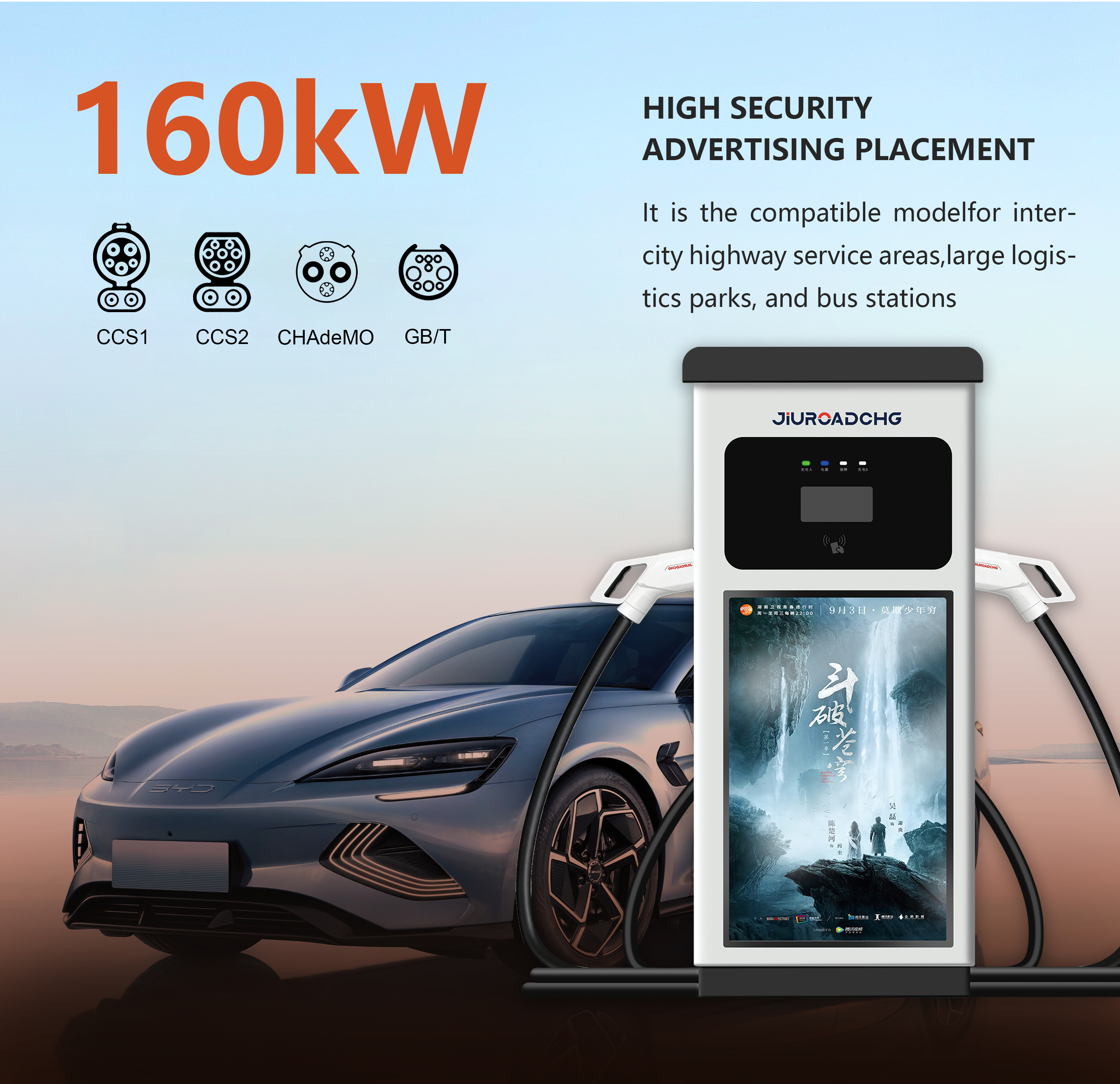
A 160kW integrated EV DC charger houses the power electronics and the charging cables within a single physical enclosure. This approach reduces trenching requirements heavily. It simplifies underground cabling and avoids complex conduit runs. Consequently, it requires a much smaller total real estate footprint. These combined traits make integrated units ideal for constrained spaces like retail parking lots or fast-food drive-through lanes.
Hardware will eventually require maintenance. Rapid serviceability dictates your network's uptime metrics. Look for units featuring front-and-back access panels. These panels should expose modular power blocks, such as individual 20kW or 30kW rectifier modules. Hot-swapping capabilities are vital here. If a single module fails, a technician can slide a new one in without taking the entire unit offline. This modular redundancy minimizes catastrophic downtime.
Outdoor longevity demands strict environmental sealing. Weather, dust, and vandalism pose constant threats to charging infrastructure. You must establish non-negotiable baselines for protection ratings. Require IP54 or IP55 certifications for the enclosure, which align with NEMA 3R or NEMA 4 standards in North America. Furthermore, mandate an IK10 rating for impact resistance. This ensures the touchscreen and casing can survive blunt force strikes without compromising internal electronics.
Many fast chargers feature two charging cables, allowing two vehicles to plug in simultaneously. However, not all dual-port chargers distribute power intelligently. A common business problem arises with static power splitting. If a charger uses a hard 80kW/80kW split, it severely underutilizes available capacity. Imagine one vehicle requests 120kW, but the second vehicle can only accept 40kW. A static split limits the first vehicle to 80kW, wasting 40kW of potential power delivery.
To maximize asset utilization, operators must evaluate how power flows through the hardware. Follow these specific evaluation criteria when assessing dual-port setups:
Dynamic power allocation ensures that every available kilowatt generates revenue and moves vehicles through the queue faster.
Procuring hardware is only one phase of deployment. Installation realities often derail poorly planned projects. Deploying multiple high-capacity units frequently triggers utility demand limits. Exceeding local grid capacity necessitates incredibly expensive transformer upgrades. These infrastructure upgrades can delay projects by several months.
Forward-thinking operators utilize alternative approaches to bypass grid constraints. DC-to-DC architectures are gaining massive traction. These models utilize DC-input chargers paired directly with solar canopies or centralized Battery Energy Storage Systems (BESS). By skipping the traditional AC-to-DC conversion step at the charger level, you eliminate inherent conversion losses. This topology creates a highly efficient microgrid ecosystem right in the parking lot.
Smart energy management protects operational margins. You should evaluate whether the charger's backend software supports advanced grid communication. Look for OpenADR compliance or direct API integrations with local energy management systems. These software layers allow the charger to automatically throttle its output during peak grid pricing hours. By shaving peak loads momentarily, you stabilize grid demand and avoid penalizing utility tariffs.
Evaluating specification sheets requires a disciplined methodology. Without a standardized shortlisting logic, operators risk purchasing non-compliant or orphaned hardware. Use the following compliance standards to filter out high-risk vendors early in the procurement cycle.
Procuring high-capacity charging hardware is a complex technical exercise. It requires carefully balancing peak power delivery against the harsh realities of thermal limits, grid constraints, and vehicle BMS bottlenecks. You cannot simply buy the cheapest unit and expect flawless highway corridor operations. Success demands a rigorous evaluation of voltage architecture, cooling efficacy, and power allocation logic.
Take proactive next-step actions before issuing a Request for Proposal (RFP). Buyers should mandate load-profile simulations from vendors to understand actual power curves. Request localized operational models factoring in peak grid demand limits. Finally, physically audit a deployed unit. You must personally assess cable ergonomics, touch screen responsiveness, and active cooling noise. These hands-on evaluations separate premium hardware from underperforming alternatives.
A: Charging is not linear; it follows a specific charging curve. A compatible 800V vehicle starting at a 10% State of Charge (SoC) typically adds 100 to 150 miles of range in roughly 15 to 20 minutes. The vehicle's battery management system will taper the charging speed heavily once the battery reaches 80% SoC to protect cell health.
A: Integrated units house both power converters and dispensing cables within one cabinet. This provides a lower installation cost but requires a larger footprint per parking bay. Split systems place the bulky power cabinet away from the parking space. This results in higher installation and trenching costs but yields a sleeker, smaller dispenser at the bay.
A: Liquid cooling is not strictly required for 160 kW, but it is highly recommended if continuous outputs exceed 300 to 400 Amps. Liquid-cooled cables prevent thermal derating during back-to-back charging sessions. They also ensure the cables remain lightweight, pliable, and fully maneuverable for all users.
A: Yes, provided the charger features a wide output voltage range, typically spanning 200V to 1000V DC. The charger intelligently communicates with the vehicle and steps down voltage for legacy 400V cars. It simultaneously delivers higher amperage to maximize power delivery without stressing the hardware.


